

EPWM of C2000
Reference given by TI’s C28x Academy: Enhanced Pulse Width Modulation (EPWM)
Local examples at [CCS]\C2000Ware[version]\driverlib\[device]\examples\epwm
Local library at [CCS]\C2000Ware[version]\driverlib\[device]\driverlib\epwm.h
LET SYSCFG DO EVERY FRICKING PART!
Access
C2000ware uses a uint32 as entrance of each EPWM module, it is often referred as base in most EPWM functions. device.h pre-defines them as marcos EPWMx_BASE. When configured with the syscfg tool in CCS, board.h will re-define them as marcos with user-determined names.
Timebase
The timer of each EPWM module is referred as a TimeBase (TB), with clock signal TBCLK pre-scaled from EPWMCLK.
EPWMCLK is the same as SYSCLK on devices without EPWMCLKDIV and can be accessed by DEVICE_SYSCLK_FREQ in device.h. (It is commented in the library that EPWMCLK is half SYSCLK at reset, no idea what that means.)
TBCLK is calculated by:
Where HSPCLKDIV and CLKDIV is generally equivalent.
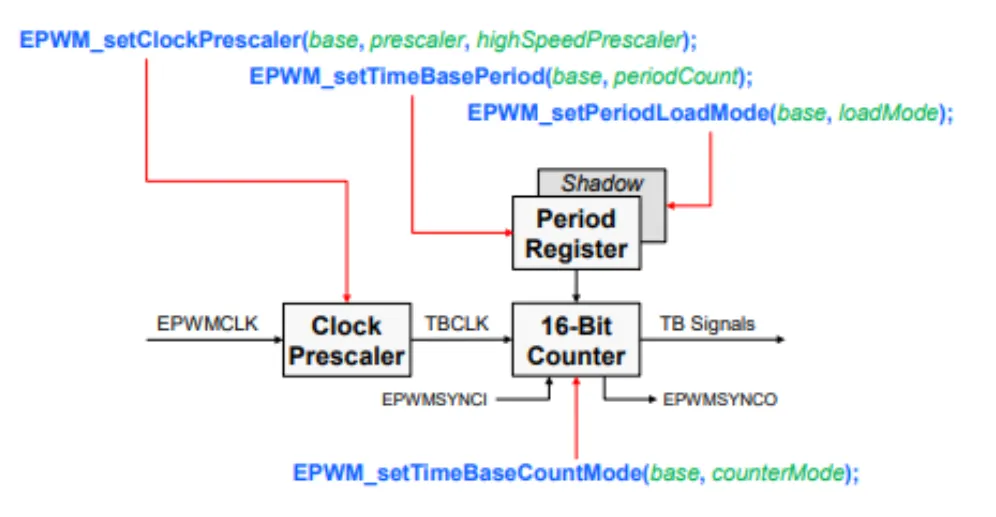
periodCount is referred as TBPRD in below. It can be shadowed to control the time of update.
// To determine where to load TBPRD from
EPWM_setPeriodLoadMode(uint32_t base, EPWM_PeriodLoadMode loadMode)
typedef enum
{
    //! PWM Period register access is through shadow register
    EPWM_PERIOD_SHADOW_LOAD = 0,
    //! PWM Period register access is directly
    EPWM_PERIOD_DIRECT_LOAD = 1
} EPWM_PeriodLoadMode;

// To determine when to load TBPRD from the shadowed register (if used)
PWM_selectPeriodLoadEvent(uint32_t base,
                           EPWM_PeriodShadowLoadMode shadowLoadMode)
typedef enum
{
    //! Shadow to active load occurs when time base counter reaches 0
    EPWM_SHADOW_LOAD_MODE_COUNTER_ZERO = 0,
    //! Shadow to active load occurs when time base counter reaches 0 and a
    //! SYNC occurs
    EPWM_SHADOW_LOAD_MODE_COUNTER_SYNC = 1,
    //! Shadow to active load occurs only when a SYNC occurs
    EPWM_SHADOW_LOAD_MODE_SYNC         = 2
} EPWM_PeriodShadowLoadMode;
Output from Internal Counters
CMPA/CMPB > Action-Qualifier Submodule -> Output
CMPx is a digital threshold. There are 4 of them in each EPWM module. CMPA/CMPB can be used to generate output in Action-Qualifier, while CMPC/CMPD can only used for Event-Trigger.
EPWM_setCounterCompareValue(uint32_t base, EPWM_CounterCompareModule compModule,
                            uint16_t compCount)
typedef enum
{
    EPWM_COUNTER_COMPARE_A = 0, //!< Counter compare A
    EPWM_COUNTER_COMPARE_B = 2, //!< Counter compare B
    EPWM_COUNTER_COMPARE_C = 5, //!< Counter compare C
    EPWM_COUNTER_COMPARE_D = 7  //!< Counter compare D
} EPWM_CounterCompareModule;
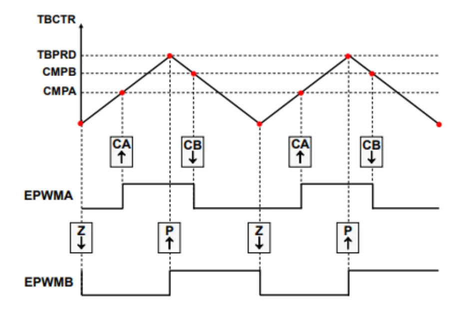
To determine how should output change according to TB and CMPx:
EPWM_setActionQualifierAction(uint32_t base,
                              EPWM_ActionQualifierOutputModule epwmOutput,
                              EPWM_ActionQualifierOutput output,
                              EPWM_ActionQualifierOutputEvent event)

typedef enum // output channel(pin) enumeration
{
    EPWM_AQ_OUTPUT_A = 0, //!< ePWMxA output
    EPWM_AQ_OUTPUT_B = 2  //!< ePWMxB output
} EPWM_ActionQualifierOutputModule;

typedef enum // action-qualifier event source enumeration
{
    EPWM_AQ_OUTPUT_ON_TIMEBASE_ZERO       = 0,      //Z
    EPWM_AQ_OUTPUT_ON_TIMEBASE_PERIOD     = 2,      //P
    EPWM_AQ_OUTPUT_ON_TIMEBASE_UP_CMPA    = 4,      //CA↑
    EPWM_AQ_OUTPUT_ON_TIMEBASE_DOWN_CMPA  = 6,      //CA↓
    EPWM_AQ_OUTPUT_ON_TIMEBASE_UP_CMPB    = 8,      //CB↑
    EPWM_AQ_OUTPUT_ON_TIMEBASE_DOWN_CMPB  = 10,     //CB↓
    EPWM_AQ_OUTPUT_ON_T1_COUNT_UP         = 1,      //T1↑
    EPWM_AQ_OUTPUT_ON_T1_COUNT_DOWN       = 3,      //T1↓
    EPWM_AQ_OUTPUT_ON_T2_COUNT_UP         = 5,      //T2↑
    EPWM_AQ_OUTPUT_ON_T2_COUNT_DOWN       = 7       //T2↓
} EPWM_ActionQualifierOutputEvent;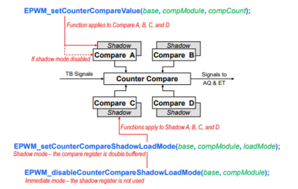
Like TBRPD, CMPxs are also shadowed. I think I will never re-configure those shadow-settings during operation, so just let syscfg handle the initiation.
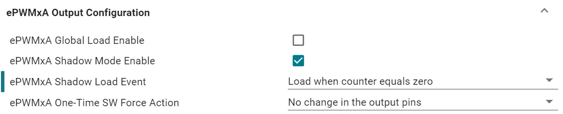
Some example projects left the Shadow Mode disabled, but I think it is rather important to prevent sudden change of duty cycle & other stuff, given that the controller function may not be synchronous with EPWM modules.
Interrupt from Event-Trigger
Like all other interrupts, this function is used:
static inline void Interrupt_register(uint32_t interruptNumber, void (*handler)(void))In EPWMx modules the interruptNumber is referred as INT_EPWMx, all of which are in INTERRUPT_ACK_GROUP3. When use syscfg to configure EPWM, the interruptNumber will be defined as INT_[name], and the corresponding ISR as INT_[name]_ISR.
To enable the interrupt of EPWMx:
EPWM_enableInterrupt(uint32_t base) // use BASE, not INTTo set the source of interrupt (Why aren’t those properly enumerated??):
EPWM_setInterruptSource(uint32_t base, uint16_t interruptSource)
//! Valid values for interruptSource are:
//!   - EPWM_INT_TBCTR_DISABLED       - Time-base counter is disabled
//!   - EPWM_INT_TBCTR_ZERO           - Time-base counter equal to zero
//!   - EPWM_INT_TBCTR_PERIOD         - Time-base counter equal to period
//!   - EPWM_INT_TBCTR_ZERO_OR_PERIOD - Time-base counter equal to zero or
//!                                     period
//!   - EPWM_INT_TBCTR_ZERO_OR_PERIOD - Time-base counter equal to zero or
//!                                     period
//!   - EPWM_INT_TBCTR_U_CMPx         - Where x is A,B,C or D
//!                                     Time-base counter equal to CMPA, CMPB,
//!                                     CMPC or CMPD (depending the value of x)
//!                                     when the timer is incrementing
//!   - EPWM_INT_TBCTR_D_CMPx         - Where x is A,B,C or D
//!                                     Time-base counter equal to CMPA, CMPB,
//!                                     CMPC or CMPD (depending the value of x)
//!                                     when the timer is decrementing
You can set how many times an event needs to occur before triggering the interrupt, clap for this one.
EPWM_setInterruptEventCount(uint32_t base, uint16_t eventCount)Dead-Band
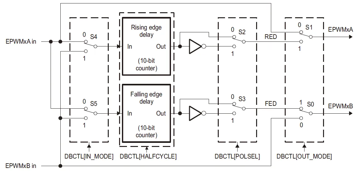
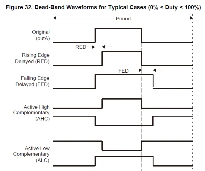
When the Dead-Band submodule is enabled, the output is generated with reference to either EPWMxA or EPWMxB, normally EPWMxA
With all those switches controlled by bits Sx, there are some modes in dead-band generation. Active-High Contemporary means we want a both-low dead-band, and that the output waveform of both channel can be mid-aligned. Active-Low Contemporary then leads to a both-high dead-band.
For example, in AHC mode, S3 = 1, S2 = 0, S1 = S0 = 1. When a rising-edge comes from , it is delayed for some time and then reaches the output A. While the falling-edge delay counter does not function and is fed to output B. Vice versa when a falling-edge comes from .
I think I would seldom edit dead-band during normal operation, so syscfg is good enough.
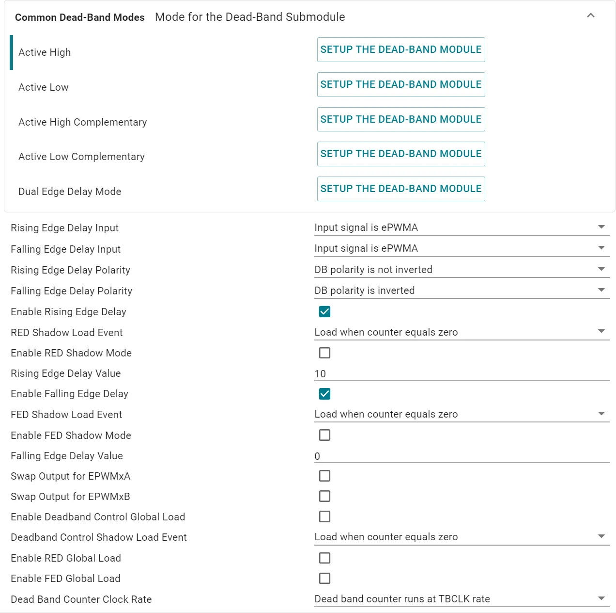
Inputfield controlsS4/S5, keep the default.Polarityfield controlsS2/S3